Sunday, August 17, 2008
 This image shows how a pen has been attached to a spacer so that the pen can accurately follow the form of the master side of the clay model. It will mark a line on the foam core to be cut and then the template can be taken to the other side of the model to define exactly where the clay will need to go on the second side. The template has been positioned agains control points on the top and the bottom to assure accurate placement relative to the center line of the car.
 This photo shows the foam core template being cut with an exacto knife. A wood template would be stronger and better but would take longer and cost more.
From Master to Second Side

The template from the master side has been brought to the second side and was used to smooth the clay so that it is accurately dimensioned according to the other side. Metal strips are put on top of the clay smoothed by two spaced out templates and then the clay is smoothed between these metal strips with a metal yard stick.
Friday, June 13, 2008
Body development continues
 Herman, Frank, and Zach continue clay surface development. Jim is taking the picture.
 This template (white foam-core material) was made to transfer the new hood height from one side to the other.
 Here, Frank and Zach have made a template of the top of the passenger compartment from the master side and have flipped it over to the other side to assure that both sides aer symmetrical. The green tape on the hood represents the location of the engine head which is the highest area on the engine. Some clay needed to be added here to assure engine clearance.
Monday, June 9, 2008
June 6, 2008 ..... Engine Mounted in Chassis
Tuesday, May 27, 2008
May 27, 2008
We have made a lot of progress since the last posting.

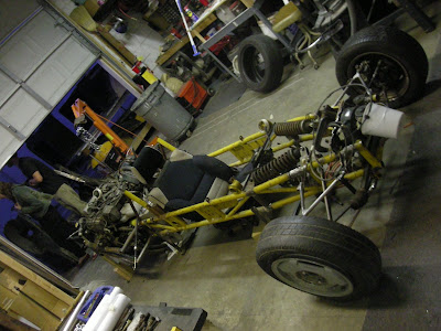
The chassis is on the ground for the first time.

We finally removed the engine and rear suspension from what was left of the MR2

Matt with the Positioning Jig he just built. He put steel up to the MR2 chassis critical engine and suspension mounting points. Then he welded the steel and drilled holes to match those on the MR2 chassis. We will use this jig to assure that our rear engine and suspension support structures and accurate and will fit the engine and suspension.
Subscribe to:
Posts (Atom)


