Sunday, August 17, 2008
 This image shows how a pen has been attached to a spacer so that the pen can accurately follow the form of the master side of the clay model. It will mark a line on the foam core to be cut and then the template can be taken to the other side of the model to define exactly where the clay will need to go on the second side. The template has been positioned agains control points on the top and the bottom to assure accurate placement relative to the center line of the car.
 This photo shows the foam core template being cut with an exacto knife. A wood template would be stronger and better but would take longer and cost more.
From Master to Second Side

The template from the master side has been brought to the second side and was used to smooth the clay so that it is accurately dimensioned according to the other side. Metal strips are put on top of the clay smoothed by two spaced out templates and then the clay is smoothed between these metal strips with a metal yard stick.
Friday, June 13, 2008
Body development continues
 Herman, Frank, and Zach continue clay surface development. Jim is taking the picture.
 This template (white foam-core material) was made to transfer the new hood height from one side to the other.
 Here, Frank and Zach have made a template of the top of the passenger compartment from the master side and have flipped it over to the other side to assure that both sides aer symmetrical. The green tape on the hood represents the location of the engine head which is the highest area on the engine. Some clay needed to be added here to assure engine clearance.
Monday, June 9, 2008
June 6, 2008 ..... Engine Mounted in Chassis
Tuesday, May 27, 2008
May 27, 2008
We have made a lot of progress since the last posting.

The chassis is on the ground for the first time.

We finally removed the engine and rear suspension from what was left of the MR2

Matt with the Positioning Jig he just built. He put steel up to the MR2 chassis critical engine and suspension mounting points. Then he welded the steel and drilled holes to match those on the MR2 chassis. We will use this jig to assure that our rear engine and suspension support structures and accurate and will fit the engine and suspension.
Tuesday, April 29, 2008
May 29 Update


Since we drastically changed the Toyoto MR2 Steering hubs we had to totally re-calculate all the steering geometries. We had to set up the "scrub radius", camber, caster, and akerman. We calculated maximum front wheel turning angles using the new steering rack we bought. This rack has a lot less travel than the stock Toyota MR2 rack. This means we have less steering wheel turns lock to lock. Now we will also have more steering effort. We have to shorten the steering arms to get the turning radius with less rack travel.
After calculating and mapping the proper pivot point for the tie rod ends, matt cut the Toyota Steering Arms and ground and welded them back to gether.


Jim and Matt studied Akerman Steering and built a two dimensional mock-up to test the steering geometry. This will assure that in a tight turn, the inside front wheel will turn the proper amount more than the outside wheel (the is travelling a smaller diameter radius in a turn). We also made a 2D graphic of the front fender to study tire clearance in a full-lock turning situation.
Monday, April 28, 2008
May 28 Update
Monday, April 7, 2008
May 7 Update
 The new steering rack can barely be seen just behind the horizontal yellow tubing. Matt Briggs was working on this when he received the tragic news that his sister had died that night. We immedietely booked a flight to Rochester New York so he could be with his family.
 Paul stopped by to help. It was his first experience working on a full size model and he noted how the scale of the tools to the size of the model is very different than working on a 1/5 scale model. Paul moved quickly and filled in new clay between the rear fenders to make more room for the Toyota engine that will eventually be under this area.
Monday, March 31, 2008
Continuing the clay surfacing
 Napoleon enjoys a well earned "fantasy" after completing the "packing" of the hot clay over the entire center body surface. Only the two front fenders remain for "packing". He used gloves because the clay is 160 degrees and can blister your hands if left there for more than a few seconds. After the clay cools, it will be very hard for final surfacing and eventual mold making.
Sunday, March 23, 2008
Applying the Surfacing Clay
 In this image, Jim is shaping the clay using a piece of spring steel that has small teeth cut into one edge. Previous to this, he roughed out the surface using a tool called a "rake" that looks a bit like a garden rake. It too is a piece of steel with teeth in it, but it is attached to a handle and is used for the initial quick cutting and shaping of the clay. It is easier to do the initial shaping of the clay while it is still a little warm. After the clay has cooled off completely, it becomes quite hard and is more difficult to shape.
 In this photo, Matt Briggs is putting billets of clay into the clay oven to heat it so that it will be soft enough to apply over the blue foam. The wood and foam structure upon which the clay is applied is called the "clay buck".
The Clay we are using was donated by Mitsubishi Motors thanks to arrangements made by Raymond Chan (a student at the Academy of Art University who interned at Mitsubishi last summer) and supported by the Academy based on the fact that several students will gain valuable experience helping to build the full size clay model.
This clay is the same clay used by the car companies for making body models. It is first heated in an oven to 160 degrees to make it soft for application to the foam. As it starts to cool, it will become more firm and hard and then can be formed using specialized clay modeling tools. When fully cooled, the clay surface becomes quite hard.
Eventually, we will be making fiberglass molds from the clay surfaces. Then we will be making fiberglass parts in these molds.
Priming the foam before applying the clay
Preparing the foam for application of clay surface
Wednesday, March 19, 2008
Monday, March 10, 2008
Progress in February
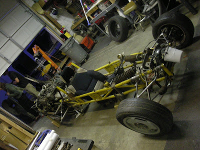
As you can see from these pictures, we have been busy working on the concept car. On the chassis, developments have been made on the front suspension geometry and we are currently awaiting a new steering rack that will fit where the lefthand drive component from the old MR2 did not.
On the body, the foam has been shaped and is almost ready for clay. Edges and certain details still need to be finished first.


On the body, the foam has been shaped and is almost ready for clay. Edges and certain details still need to be finished first.


Wednesday, February 27, 2008
First entry
Here on this blog we will post progress on current projects (as far as we can) and matters of interest.
We currently have a lot of cool things happening we think many people would find interesting, or perhaps you have a project yourself you would like to bring to life.
Beside developing consumer products, Shook design has extensive experience in automotive design and development something that is unique in Northern California.
Shook design also use energetic young creative students that combined with experienced professionals provide working solutions.
Subscribe to:
Posts (Atom)


